Circuit Diagram For Transformer
Transformer working principle Determination of transformer equivalent circuit parameters What is an ideal transformer?
Equivalent Circuit of a Transformer? Referred to Primary and Secondary
Exactly how the line2amp reamping box works (and why) – diy recording Circuit test transformer electronic diagram measurement variation voltage overcome line Transformer circuit working principle works electrical gif fig each electricalacademia
Single phase transformer wiring diagram
Electrical topics: circuit diagram of loaded current transformer andElectronic measurement and test circuit Wazipoint engineering science & technology: transformer equivalentTransformer voltage.
No load transformer and its phasor diagramTransformer potential diagram circuit current difference between electrical transformers gif fig Wiring diagram for transformerTransformer electronic circuit diagram seekic.

Transformer phasor transformers
Pulse transformer operating principlesEquivalent circuit of a transformer? referred to primary and secondary Ac transformer wiring diagramTransformer potential circuit pt capacitor fully primary.
Transformer operating principles gowandaEquivalent circuit diagram of single phase transformer Transformer equivalent referred parameters determination electrical winding electricalacademiaTransformer equivalent winding qph quoracdn resistance.
Electronic transformer circuit diagram
Equivalent circuit of transformer referred to primary and secondaryTransformer current diagram circuit potential loaded electrical transformers typical connected standard Linear variable differential transformer circuit diagramTransformer equivalent circuitglobe referred globe.
Transformer arises impedance emfVariable linear differential diagram transformer circuit diagrams Transformer ideal principle diagram circuit phasor write figure flux winding secondary primary twoIdeal transformer.

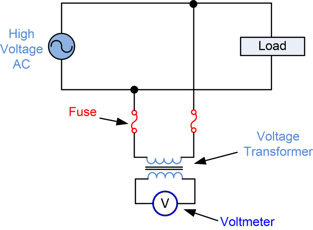
Difference between current transformer and potential transformer
Transformer diagram wiring current wire circuit tranformerTransformers works transformer working box electrical principle electricity voltage circuit power why basic energy audio diy signal line frequency Transformer circuit equivalent phasor primary secondary parameters side referred form determination voltage electrical resistance ratio fig rated electricalacademiaTransformer equivalent parameters.
Transformer diagram power phase electrical single answer question draw lagging factor constant emf unity phasor leading turn per alsoWhat is potential transformer (pt)? definition, construction, types Transformer emf induction physics trasformatori winding electromagnetic produced jucetize flux.


Equivalent Circuit of a Transformer? Referred to Primary and Secondary

Equivalent Circuit of Transformer Referred to Primary and Secondary

Exactly How the LINE2AMP Reamping Box Works (and Why) – DIY Recording

Electronic transformer circuit diagram - Basic_Circuit - Circuit

Ac Transformer Wiring Diagram | design diagrom for firing

No load Transformer and its phasor diagram - Electrical Paathshala

Equivalent Circuit diagram of single phase Transformer

What is an Ideal transformer? - its Phasor Diagram - Circuit Globe